Lattix Architect Data Model#
Any system or system of systems can be represented in a DSM as hierarchical groupings, referred to as Partitions or Subsystems. Each Subsystem or Partition is represented by a row and corresponding column in the DSM.
Each leaf level Subsystem contains an Atom to which Dependencies are established, either manually by the user or defined in a data source (such as Excel or XML). Both Atoms and Dependencies can be classified by user-defined Kinds and have any number of Properties assigned to them.
To better understand how to model your system data in a Lattix Architect DSM, please review the following descriptions and examples of the model elements:
Subsystems and Atoms#
Subsystems are the logical elements of the model which represent the hierarchical decomposition of the system. At the lowest level of each hierarchy is the leaf Subsystem which contains an Atom. Any number of leaf Subsystems can be contained by a Parent Subsystem at the next higher level of the hierarchy. Each Subsystem is represented in the DSM as a matching row and column, and Parent Subsystems are identified by a + symbol which can be selected to expand the hierarchy:
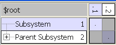
The name of each Subsystem is typically used to uniquely identify it and distinguish it from other Subsystems. Subsystems can be created manually using the Create Subsystem command or can be loaded into the Lattix project by use of the LDI Module. Parent Subsystems can be created for a selection of Subsystems by using the Create Parent Subsystem for command or by drag-and-drop of one Subsystem into another.
Atom Kind#
Atoms can be assigned an Atom Kind which identifies the different kinds of atoms in the chosen system. In the example below, the user has manually defined two atom kinds, “person” and “process” which have been applied to the atoms “John” and “ActivityA” respectively:
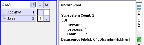
The Atom Kind can be used to selectively view Atoms and Dependencies in the DSM or to apply filters in setting rules or conducting searches. Note any Atom which has been created manually will automatically be a “manual” Atom Kind by default, while Atoms imported via a module will automatically be designated by that module name.
Domains#
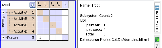
Domains are top-level Subsystems in which all of the Atoms are of the same Atom Kind. A DSM composed of multiple Domains is referred to as an MDM. In the example below, the MDM consists of two Domains, “Process” and “Person”, as illustrated in the Information panel.
Atom Properties#
Atoms can be assigned any number of user-defined Atom Properties. The Description property is a special property which can be edited by right-clicking on a Subsystem and selecting Subsystem Comments…. Tags are another special property which can be applied to a selected Subsystem or Atom (see Tagging and Impact Analysis in the Lattix User Manual for more information).
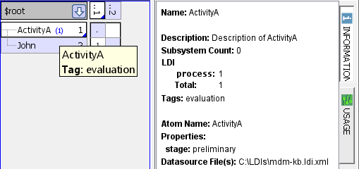
In this example, ActivityA has been selected and in the Information panel the user-defined property “stage” is displayed with a value of “preliminary”. Note also that by placing the cursor over the “(1)” tag indicator in ActivityA, the value of the tag is displayed.
Dependency#
A Dependency is established from a Source Atom to a Target Atom if the Source Atom “uses” the Target Atom. In the example below, Activity B is the Source Atom because it “uses” or “depends-on” the Target Atom, Activity A. Another way to express the dependency is that the Target Atom is “used-by” the Source Atom.
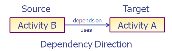
Note that the arrow that indicates the direction of the dependency goes from Source Atom to Target Atom. However, an arrow that indicates the sequence or flow of information from the Target Atom to the Source Atom is actually reversed:
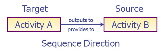
In the sequence direction, the Target Atom “provides-to” the Source Atom which “uses” its output. When modeling a sequence of activities or tasks in Lattix, it is very important to realize the difference between dependency and sequence direction in order to assign the dependency to the correct Atom.
For the example above, in the corresponding DSM which is configured with dependencies across the row and provider Subsystems at the top, the Target Atom, Activity A, begins the sequence and provides to the Source Atom, Activity B:
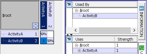
By selecting the cell with dependency indicated, the Usage panel will display the Source Atom in the upper section and the Target Atom that it “Uses” in the lower section.
Dependency Kind#
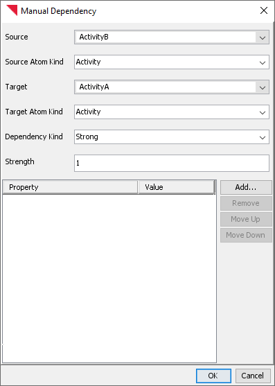
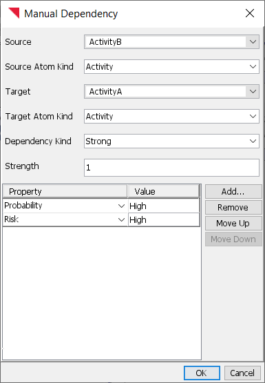
A Dependency can be assigned a Dependency Kind which identifies the different kinds of dependencies that have been defined for the chosen system. In the example below, the user has manually defined a Dependency Kind, “Strong”, which has been applied to the dependency of Activity B on Activity A:
The Dependency Kind can be used to selectively view Dependencies in the DSM or to apply filters in setting rules or conducting searches. Note any Dependency which has been created manually will automatically be a “manual” Dependency Kind by default, while Dependencies imported via a module will automatically be designated by the kinds defined by that module.
Dependency Properties#
Dependencies can be assigned any number of user-defined Dependency Properties. Each instance of a Dependency Property is also assigned a value by the user. In the example below, the user has manually defined the Dependency Properties, “Probability” and “Risk”, each with a corresponding value of “High”:
By selecting the cell with dependency indicated, the Information panel will display the Dependency Properties and values, as shown below:

This communicates that the probability of that Strong dependency occurring is high and, if it does, then the risk to the project is high. Of course, numerical values on a user-defined scale could also assigned instead of qualitative values so that calculations could be performed.
Dependency Strength#
Each Dependency is assigned a positive integer value, with “1” being the default value. The user can assign values according to a scale, such as 1-10 to indicate the relative strength of the Dependency. The display of Dependency Strength in the DSM can be configured in a variety of ways (see Configuring Dependency Strength for more information), but the most common is the Usage display which shows the total number of Dependencies. In the example below, two Dependencies of different strengths have been aggregated in the selected cell of the DSM:
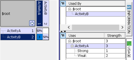
Note that the Usage panel will display Dependency Strengths of each kind of Dependency in the “Uses” section.