Working with the Conceptual Architecture Diagram (CAD)#
The Conceptual Architecture Diagram (CAD) is one of the primary ways to visualize a project within Lattix. It is easy to understand and communicate. It shows at a glance what the big building blocks of a system are and how they are related to each other.
It’s also called a “box in a box diagram.” The diagram shows the hierarchical decomposition in the form of boxes; when you expand a box you see the subsystems within that box. The placement of boxes is suggestive of either a layered or a peer relationship. Just like the DSM, you can also apply partitioning algorithms to the CAD. The boxes are then laid out in a way designed to show you the result of the partitioning. You can also edit the conceptual architecture.
Used in combination with DSM, it works as a powerful tool for communicating the architecture.
Creating a CAD#
On Project Home click on the New Conceptual Architecture link. A new CAD is created with $root as the outermost container.
Select a subsystem in the Navigator, right click and select the New Conceptual Architecture menu item. A new CAD is created with the selected subsystem as the outermost container.
Select a subsystem in a DSM or CAD, right click and select the New View –> New Conceptual Architecture menu item. A new CAD is created with the selected subsystem as the outermost container.
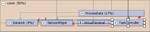
Options for Line Display#
You can view Dependency Edges by selecting View –> CAD Lines –> Show CAD Dependency Lines. For the displayed subsystems, there is a line (or an edge) indicating dependencies between them.
You can view Violations by selecting View –> CAD Lines –> Show CAD Violation Lines.
You can filter by the direction of lines by selecting View –> CAD Lines –> Show Leftward, Rightward, Upward, Downward Lines. Typically, downward or rightward lines are “good” dependencies, whereas upward or leftward lines are “bad”. These lines are independent of any other rules that are set.
Understanding the Conceptual Architecture Diagram#

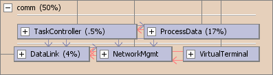
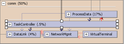
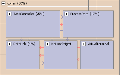
A Conceptual Architecture Diagram is a diagram of nested boxes connected by lines. The boxes represent subsystems and the lines between them represent the dependencies. A box can be expanded to display the subsystems contained within it by clicking on the ‘+’ icon in that box. Boxes can be resized and moved around.
Each box can contain layers which are indicated by layer boundaries. Typically, layers represent one-way dependencies. Subsystems within a layer can be laid out in a row, multiple rows, or even at different locations within the layer.
Lines between boxes represent dependencies. When a box is selected all the lines connecting to that box are highlighted. The lines that are red are possible bad dependencies that means that you have a dependency that is going up or to the left in the hierarchy. For the red lines to be accurate you should partition the CAD first. The strength of the relationship is also displayed.
The property panes on the right are context sensitive to the selection in the CAD.
Manipulating the Conceptual Architecture Diagram#
When you create a CAD for the first time, it displays the current state of the subsystems. The boxes are organized alphabetically when it is opened for the first time.
The CAD is a graphical editor. A box can be moved by selecting it, holding down the left mouse button and dragging the box to a new target location. A box can be also be resized by grabbing on the handles on the edge of the box. New layers can be created. Algorithms can be applied to the selected box. It is possible to Undo and Redo the modifications that have been made during a session.
The empty space can be manipulated easily to create well-aligned and visually appealing diagrams.
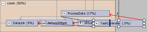
Moving a Box Relative to Another Box#
Drag the box near another box choosing the edge of the target box. If the right edge is selected, the box will be placed to the right of the target box; if the left edge is selected the box will be placed to the left of the target box; if the top edge is selected the box will be placed at the top of the target box; if the bottom edge is selected the box will be placed at the bottom of the target box. The resulting box will have the same dimensions and be in the same layer as the target box.
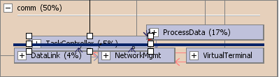
Moving a Box to a New Layer#
Select the layer line to move the box to a new layer. To move a box to another layer at the bottom, move the box near the edges of the box and you will see a long blue line displayed. This allows you to create a new layer at the bottom.
Resizing a Box#
Select a box and you will see eight handles (small squares on the boundary of the box) displayed.
Move the cursor to one of the handles in the middle of one of the sides to resize the box in a horizontal or vertical direction. Move the cursor to one of the handles in the corners to resize the box both horizontally and vertically.
Manipulating the Empty Space#
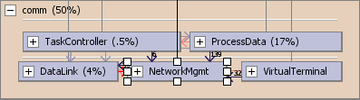
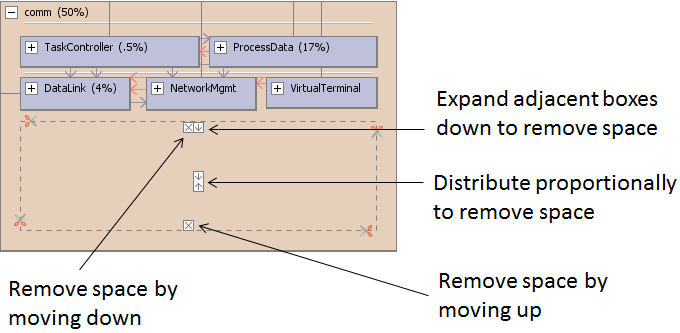
As you move and resize boxes, there will be empty space in the CAD. If you click on the empty space you will see an empty space rectangle, with icons in it. Clicking on those icons allows you to move edges and resize boxes.
Removing Empty Vertical Space#
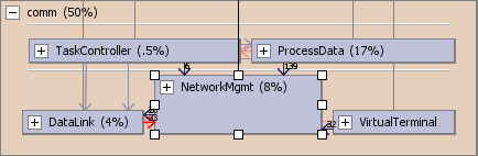
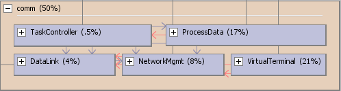
Here is the result of clicking on the Proportionally Distribute icon:
Removing Empty Horizontal Space#
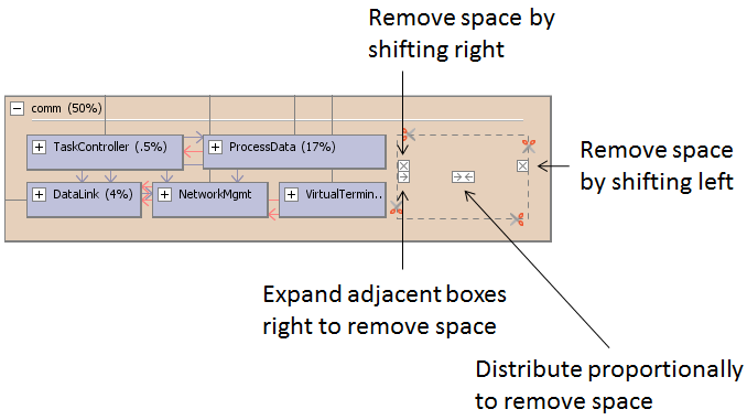
Here is the result of clicking on the Proportionally Distribute icon:
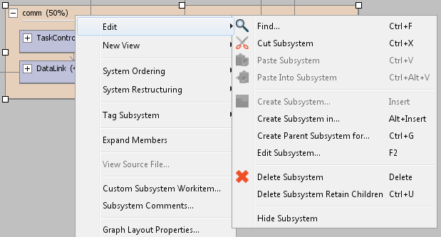
Other Operations#
All other normal editing operations such as Create, Rename, Delete, Hide are available in the CAD. Select a subsystem and right click to bring up a context menu. Select Edit to display the menu items for various operations.
Applying Algorithms within Conceptual Architecture Diagrams#
Lattix provides a rich set of algorithms for architecture discovery and management. They help identify layering and componentization within the software system even after architectural intent has eroded. Large systems can be analyzed quickly by applying many of these algorithms and coupling them with an understanding of the software system being analyzed.
In order to apply a partitioning algorithm:
Select a subsystem.
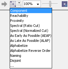
Pull down the appropriate algorithm to apply from the partitioning icon on the toolbar.
The results of the partitioning algorithms are displayed as boxes within layers in the CAD. Here is an example of how the results of the Component and Partitioner are displayed within the CAD:
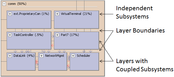
Here partitioning helps determine:
Layering: The layered view of partition groups (called virtual partition) where the higher layer depends on the lower layer but not the other way round.
Strongly (or cyclically) connected components: These are the subsystems that are interconnected in such a way that there exists dependency links to go from one subsystem to another.
Independent Components within a layer: These are subsystems within a layer which have no dependencies on each other.
Additional partitioning algorithms are described here.
Additional restructuring algorithms are described here
Other algorithms are described here.
Setting Rules with the Conceptual Architecture Diagram#
You can create layering rules from the Conceptual Architecture Diagram. First, layout the boxes within a subsystem into desired layers. Now select that subsystem in the CAD, right click, and choose the menu item Create Layering Rules.
The layering rules for the selected subsystem will be created. You can edit or change those rules further in the DSM.